
When engineers talk about “tactile feel,” they are really talking about a controlled combination of operating force, actuator height, and internal contact design. Choosing the wrong tactile switch can lead to missed actuations, poor ergonomics, or early failure in the field.
This engineering guide walks through the key parameters you should review before locking a tactile switch into your PCB: force range, actuator height, lifetime, and mounting method. It is written for industrial, appliance and control-panel applications where reliability matters more than lowest possible cost.
1. Understanding Operating Force (100–250 gf typical)
Operating force is the force needed to move the actuator from its rest position to the electrical contact point. For most general-purpose tactile switches, you will see ranges between 100 gf and 250 gf.
- Low force (≈100–130 gf)
• Light touch, suitable for handheld devices, small control panels
• Reduced finger fatigue, but higher risk of accidental actuation - Medium force (≈160–200 gf)
• Good “click” feedback for most industrial and appliance HMIs
• Balanced between comfort and mis-operation avoidance - High force (≈220–250 gf and above)
• Used where false triggering is unacceptable (safety, reset, mode change)
• Requires clear, deliberate press from the operator
When building a user interface, it is common to mix forces within the same panel. For example, navigation keys may use 160 gf, while “Start” or “Emergency Stop confirmation” keys use 230 gf to avoid accidental presses.
2. Force Curve Families: T / V / X / W / Y / Z
Beyond the peak force value, the force-travel curve also defines how a button feels. Different tactile switch families use distinct dome structures to shape the curve, often categorized as T, V, X, W, Y or Z types.
- T / V curves – quick snap, strong tactile feedback; preferred for clear “click” feel
- X / W curves – smoother increase and release; good for quieter, softer interfaces
- Y / Z curves – customized profiles where a long pre-travel or damped release is needed
When comparing part numbers across suppliers, do not rely only on the nominal force. Look for force-travel graphs in the datasheet and choose a curve that matches your product’s brand feel: sharp and responsive, or soft and quiet.
3. Actuator Height: 4.3–15 mm and Surface Alignment
The actuator height (often between 4.3 mm and 15 mm) determines how the button aligns with your panel, overlay or keycap.
Key design points:
- Match height to enclosure stack-up
Consider PCB thickness, overlay, and any keycap or silicone rubber. The actuator should sit slightly below the final surface to avoid constant pre-loading. - Avoid side-loading
If the actuator is too tall relative to the support structure, users tend to press at an angle, creating side-force and shortening lifetime. - Design for tolerance stack-up
Plan ±0.1–0.3 mm of tolerance in plastic parts, gasket and PCB. When in doubt, prototype with two heights (e.g., 7.0 mm and 9.5 mm) before freezing the mechanical design.
A simple rule: the taller the actuator, the more critical mechanical guidance becomes. Consider adding plastic guides or keycaps that transfer force vertically into the switch.
4. Designing for Lifetime: 100k Cycles and Above
Many general tactile switches are rated for 100k mechanical cycles or more. For consumer interfaces, this may be sufficient. For industrial control, HMI panels, or elevator-style usage, you may want to design in more margin.
To extend real-world lifetime:
- Keep the switch within its rated force and travel
- Avoid continuous pre-load from stiff overlays or warped panels
- Control ESD and surges on the signal lines if they connect to long cables
- Protect the switch from contamination (dust, oil, moisture) using IP-rated versions when necessary
For mission-critical functions, consider derating: if the spec says 100k cycles, design the application as if you only had 50–70k cycles and monitor how often the function will be used.
5. PCB Mounting: Through-Hole vs SMD
Tactile switches come in both through-hole (TH) and SMD versions. The choice is not only about assembly cost.
Through-Hole (TH)
- Stronger mechanical retention, especially for high operating force
- Tolerates manual operation, heavy keycaps, or vibration
- Common for industrial panels and appliance front boards
SMD
- Compatible with reflow soldering and high-volume SMT lines
- Allows both top-actuated and side-actuated versions
- Works well for compact consumer and IoT designs
If the switch will be pressed directly by the user through a rigid panel, TH versions or reinforced SMD footprints (additional mechanical pads) are recommended. For light-touch buttons under a membrane overlay, SMD is often sufficient.
6. High-Reliability Use Cases
Tactile switches are widely used in:
- Industrial control panels and PLC interfaces
- White goods and commercial appliances
- Medical devices (non-critical functions)
- Test and measurement instruments
- Automotive interior modules (where specs permit)
In these applications, force, height and mounting work together. A well-chosen tact switch will support the product throughout its life with consistent feel and low field returns.
7. Next Steps: Review Options and Talk to Engineering
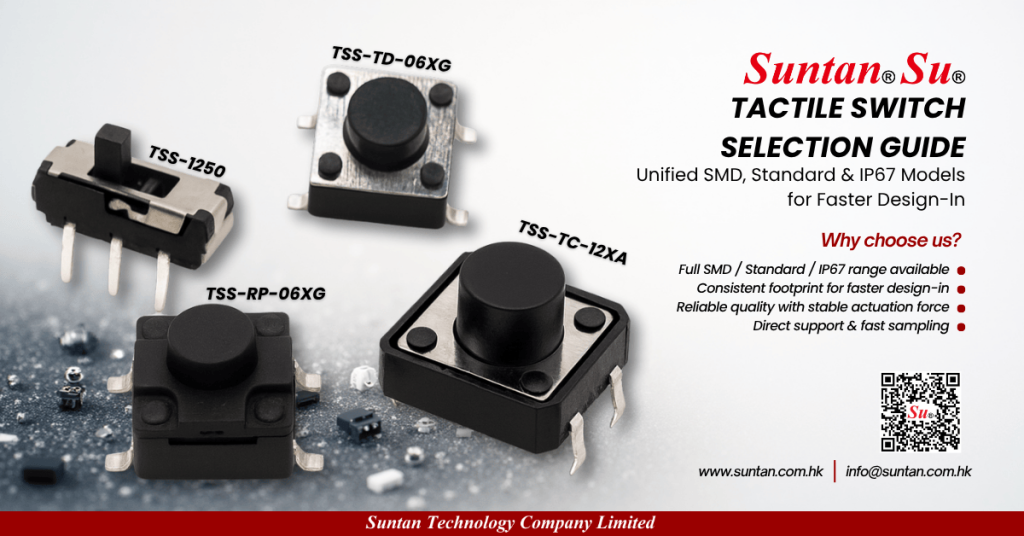
Suntan provides a full tactile switch portfolio covering different operating forces, actuator heights from 4.3–15 mm, and both TH/SMD platforms to match your HMI design.
- Explore tactile switch families and datasheets
- Discuss engineering details or request samples:
Email info@suntan.com.hk or send your project information via our contact page
Read Full Engineering Guide → and align force, height and reliability before you tape-out your next PCB.